Travelers.

October 18, 2023

Travelers, in the plural, and I don’t mean the travelers among us, but the structures for the mainsheet traveler and self-tacking jib. Both of them gave me a bit of a headache.

During the construction of Fram, I was convinced that I would create a round mainsheet traveler. The radius would be approximately the length of the boom. Therefore, the aft deck is also equipped with high-density foam in the right place and in the right shape.

However, the more I thought about it, the more I began to dislike the idea due to its complicated construction and the additional costs, especially when the benefits were only marginal.

Several multihull sailors use a relatively simple system in the form of a double sheet in the shape of an inverted “V”, also known as an “Oceansheet.” . For a long time, that seemed like a good option, especially because it’s relatively easy to implement. However, I saw on one of the F36 trimarans how the laminate deformed at the location of the blocks. The forces on such a single point are very significant, and the deck needs to be further reinforced in that area. Well, I didn’t really want to deal with that either, and an “Oceansheet” also has its drawbacks.

Long story short, I ultimately chose a traditional mainsheet traveler, and I recently made the base for it. You can read a detailed report about it on my website. The construction is still without the Ronstann series 30 track. I will add these later.

The traveler for the high aspect jib was also a bit of a challenge. From the outset, I wanted, among other things, to have a self-tacking jib. One of the great advantages of a trimaran is that it is more than an excellent sailboat concept, you could say it’s a sailing machine. In order to fully exploit that as a short-handed crew or solo sailor, the systems must work perfectly and be easy to use. Tacking frequently in narrow waters becomes child’s play with it.

Ian Farrier has provided such an option, but he associates it with the need for a centerboard. A daggerboard, in his design, protrudes above the deck and in front of the mast. Right in the place where a self-tacking jib’s traveler track is normally positioned. A centerboard does not extend above the deck and thus does not obstruct the traveler.

For me, the advantages of a centerboard do not outweigh the disadvantages. That’s why I consciously chose a daggerboard. I solved the “problem” of the daggerboard protruding above the deck by placing the jib’s traveler track in front of the daggerboard case. To ensure this doesn’t compromise a smaller jib, I equipped it with a boom, a “jib boom,” in other words. In fact, this makes the trim options for the jib the same as those for the mainsail.

Another option could have been to widen the space just in front of the mast step by making adjustments to the mast step and the head of the daggerboard. I didn’t want to do that, especially since I want to experience the practical benefits of a jib boom.

The downside to the jib boom is that it does make the foredeck a cluttered and unsafe place to be, but I ensure that I don’t need to be there and can trim everything from the cockpit. In addition, I ensure that the boom can be well controlled under all conditions with the jibsheet, topping lift and the traveler control lines.

I carried out the construction parallel to that of the mainsheet traveler, and the structure is the same, although lower and narrower. The Ronstan Series 30 track is 2 meters long. Please click here to jump to the relevant chapter on my website.


Windlass.

April 21, 2020

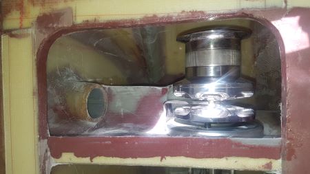
In an earlier post I told you about my windlass choices. Now that I am finishing the interior it is also time to put the windlass in its final position. For that I have to make the base plate on which the winch is mounted.

20200328_171024_450

My Quick Rider windlass is deliberately delivered without anchor chain guide as I want to turn the windlass counterclockwise. All winches have the anchor chain guide on the other side. So I made the anchor chain guide myself from fiberglass over a mold. The base plate for the windlass has thus become quite a special workpiece.

20200404_103500_450

Of course, the anchor chain locker is closed with a neat door that matches the rest of the interior

20200406_153405_450

More photos can be found in the updated album


Three hulls coming together.

February 14, 2018

Three hulls coming together in three exciting moments.

The first one, aligning the lower folding struts with each other and in square relation to the mainhull. The distance difference between the for and aft lower folding strut at the inner end and the outer end is 6mm. on Starboard and 2mm. on Port. This means that the alignement of the carbon folding anchors in the mainhull is quite good. A great achievement and kind of reassuring for the next steps.

20171202_175552_450

The second one, first trial of the folding system. It works great !

FoldingAnimation

The third one, the final assembly of my trimaran. The transformation of three hulls and four beams into a boat is the climax of the construction. Finally everything comes together and leads to the trimaran I dreamed of. It is definitely a highlight of the construction so far. Although seeing her full beam for the first time is a bit intimidating …

20180127_150504_450

You can find much more photos in this gallery.

And this and this video on my youtube channel


Floats down to Earth.

October 21, 2017

Dsc01496_450_aged

It’s been a long time since we hung the first float under the roof, followed by the second one. All those years they have collected only dust but now they can come down again.

20171017_172042_450

Something has changed.

20171008_111355_450

The port float is hanging above and behind the boat. To bring down the port float I first had to make room next to the boat. The boat has to slide sideways to create ample maneuver space for the forklift. With the help of two pallet jacks the boat easily slides sideways.

20171008_132909_45020171008_135436_450

With a makeshift boat-stand clamped to the forklift I carefully lifted the float, unscrewed the tensioning straps the floats were hanging in and bring it down. However, maneuvering with forklift and boat only takes one way. The port float is still looking in the wrong direction but turning is not possible because of lacking space. The workshop crane brings the solution.

20171008_145810_45020171008_150408_450

In the free space somewhere in the middle of the workshop height, I can turn the boat in the right direction and bring it back to the position at the port side of the center hull.

20171014_104800_45020171014_123413_45020171014_131026_450

The other float is much easier to reach and is already hanging in the right direction. There is still not enough maneuvering space for the forklift but taking it over by the workshop crane brings the float to its position at the starboard side of the center hull.

20171008_162008_45020171015_232833_450

After all the dust has been removed, the first work is putting the floats upside down for applying the Coppercoat anti-foul.


More fairings

August 2, 2016

More fairings, now on the starboard side.

dbC00030_450

dbC00031_450.jpg

Vacuum bagged first foam layer.

dbC00038_450

dbC00039_450.jpg

Building up the thickness with more (screwed down) foam layers. I decided to make a fairing on the front and bottom side of the escape hatch to minimize water pressure on the hatch.

dcc00046_450

This hatch recess was made for a Lewmar safety hatch, however, this type of hatch is not available anymore and instead I bought a Vetus Magnus hatch which is also suitable to mount in this location. However, size and hinges are slightly different from the Lewmar  and so I had to make some modifications to the recess and hull.

dcc00047_450

While doing this, I also decided to cut away the aft part of the recess in line with the other fairings. (at the cost of a lot of itch on hands and arms 😦

dcc00056_450

Structural integrity has been restored by adding some extra laminate.

dcc00057_450.jpg

All hull fairings are now finished.


Beam strut fairings

July 5, 2016

Before starting the filling and fairing of the outside of the hull a streamlined foam patch must be added to the front of the beam struts.

Adsc00174_450

The first foam layer has been glued to the hull with the pressing help of a vacuum bag.

Adsc00176_450

Then the next layers are easily being screwed down.

Adsc00184_450

The final fairing still without a layer of glass laminate.

Adsc00187_450

And of course the same fairing but a little smaller for the aft beam strut.

Dsc00006_450

After adding the laminate around these fairings the filling and fairing proces on the outside of the hull has begun.


High time for an update !

June 19, 2016

My last post was from December 2015. I am ashamed.

It seems as if nothing has happened, but on the contrary, I have been very busy and have made good progress. But to be honest I have not had a lot of inspiration for updating my blog and website. Perhaps also because of the fact that lately I share my build adventures also on a Dutch sailors forum, which is again time consuming but at the same time much easier writing for me than in the English language. Google translate is still my best friend 😉

There has always been a demand for a Dutch version of my blog and website but I could not find an easy way to do this. So I found this alternative solution by sharing my building adventures on this Dutch sailors forum. My contributions regarding the building of Fram can be found with this link.

A recently sad event is that my dear mother passed away. Next month she would have been 98 years old, a respectable age for a respectable lady. We have organized an impressive funeral for her where she would have been proud of. We have cleared her cozy apartment and distributed her personal belongings and preserved for posterity as good as possible.

Sometimes some things are more important than building a boat.

You would have not expect it by the limited updating of my blog, but 2015 was a record breaking year regarding the hours (850) I’ve spent on building my boat.

Normally at Sunday’s I’m working on the boat. But not today, today is Father’s day. I have had a nice family afternoon and for the rest of the day I finally found some time to provide an update for my website.

The following photo galleries has been reorganized and provided with new photo’s:

Aft cabin and cockpit construction

Finishing the stern

Transmission steering system

Waterballast tank

And I have added a new chapter called “Aft cabin interior”.

Do not forget to refresh these pages in your browser (F5)


Below deck drainage of hatches

January 25, 2016

With the hull now upside down it is much easier to make the below deck drainage of the deck hatches.

Click for photo gallery

At first I had the idea of molded gutters and I did made them. In hindsight this was a bad idea, they do not fit very well and an acceptable finishing will be time consuming.

Click for photo gallery

A PVC hose does a better job and is laminated against the underside of the deck and connected to a short piece of fibreglass tube through hull and through the molded hatch recess.

Dsc00135_450

For the underdeck drainage of the foredeck hatch I choose for two straight fibreglass tubes.

Dsc00120_a_450

Also under the bridge deck in the aft cabin one straight fibreglass tube is reponsible for the drainage of water coming from the cockpit seats as well from the aft cabin hatch.

You can find a photo gallery with much more photo’s here.


Upside down again.

December 15, 2015

So, another milestone, the constructive work on the outside have been declared ready. The work on the outside of the mainhull, except for a few small details, is done and the hull is ready to be primed and painted. However there are still a few more constructive things to do inside, especially under the aft cabin bridgedeck where a further strengthening with UD glass is necessary to absorb the compression loads from the rear beams.

In order for it to let gravity no killjoy, I have therefore turned over the hull once more. Also at the inside of the cabin roof are some chores to do, such as the installation of drainage channels for the flush deck hatches. This upside down position comes also in handy for a part of the putty and paint work on the outside  (and maybe inside cabin roof).

I have thought it out very well on how I’m going to manage this on my own (and safe). Lifting and twisting such a big hull is always a little exciting but I don’t want anyone else around, that would only distract. It took me the whole Saturday but it was worth it 🙂

Getting here in late afternoon was tiresome, but then it went fast.

A little trick to get the hull to the other side.

Almost there, piece of cake ….

…. and done


Houston, we have a problem …

December 1, 2015

Dsc00015_450

In this stage of the build the rudder connection fits nicely.

Dsc00045_450

Before closing of the rudder connection compartment I did a final check at mounting possibilities of the tiller ….. and discovered my miscalculation.

Dsc00052_450

Off course I knew that the connecting bolt would not fit through the tiller opening, but I overlooked that the internal height of the rudder connection compartment is also not high enough for the length of the bolt (4″) to mount the tiller to the lever shaft.

Dsc00047_450

After a brief internal consideration my solution is a small recessed pit that gives space to the connection bolt. No drama furthermore.

IMG_1346_450

The cardboard core of a toilet roll proved to be a fine (“quick&dirty” easy to remove) mold for making a small pit with flange for mounting underneath the rudder connection compartment.

IMG_1344_450

And this is how that looks, still in trial fit stage.

Dsc00049_450

View from above with the connection bolt in the pit. I made a plug to close off the pit after mounting the bolt.

Dsc00087_450

The transmission steering system is now finished and the transom is definitely closed. The access to the rudder connection compartment is from inside trough a small hatch.

You can find the latest update of the photo gallery here.