Single side infusion on a foam hull (mold)

December 25, 2011

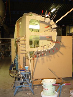
On one of the boat building forums there was a question about the practical aspects of doing a single side infusion and where the foam hull is the airtight mold. This for sure requires a meticulous job on the foam hull, preventing any piercing by screws, or repairing these very thoroughly, and a lot of attention for the bog in the joins between the foam sheets. It is good practice to use as large as possible foam parts to minimize the amount of seams. To be sure that the joint is airtight, I treat them in four stages. The first one is widening the seam with a Dremel tool and routing a V-shape in it. Then I fill these with a thick mixture of epoxy, aerosill and microballoons, the second layer a little thinner and the final layer again a little thinner. Of course this requires extra time, but doing this well is very important for the integrity of the vacuum bag. Taking shortcuts in this phase will lead to the nightmare of not getting enough vacuum for the infusion. In that stage it is too late for making repairs and the decision has to be made to give up the infusion and to go back to the hand-lay-up job.

Of course  the single side infusion on a foam hull requires a closed cell and airtight foam. The A quality Corecell foam is a fine example of such a foam. The thickness I use is 15 mm (5/8″) Thinner will be more difficult and thicker must be easier in regards to making an airtight foam mold.

Have a look at the figures below to get an idea of the (extra) hours for making the foam hull (mold) and to infuse the internal hull laminate.

Single side infusion setup hours

You can see there is a kind of learning curve. Only the last hull (Main hull port half) is made in the new workshop. The difference in working hours between the cramped workshop in my garage at home and the very comfortable and roomy workshop I have today is not very dramatic. All work has been done on my own. Working with two people is more efficient and I guess will save at least 25%.

This table and other statistics has been updated in this page on www.fram.nl

In the mean time I’m working hard (well, not today 😉 to get the main hull ready for the infusion of the external laminate. I hope to be able to do this in the first week of January 2012

Merry Christmas to all !


F-40 instead of F-39 trimaran ?

January 30, 2011

I made the second (Port) main hull half a little longer in the stern. This was not possible in my previous workshop due to the lack of space. After joining the two halves I decided to make an extension on the Starboard half to make both hull halves the same length. I don’t know yet if I will leave the hull one feet longer, but doing this now in this stage is quite easy and I can always decide afterwards to cut it off.

Click for photo gallery

The installation of the prop shaft is now ready and some new photo’s are here.


Foam main hull half finished.

May 3, 2010

Progress of the F-39 build is going quite well. Although I’m building in my spare time for quite some years now, the estimated average building hours by Ian Farrier seems to be quite accurate and I’m still on schedule with this.

Click for photo galery

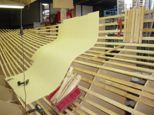
Last weekend the second main hull half has been foam stripped. The method of vertical foam stripping is one of the great inventions of Ian Farrier and after finishing 6 hulls it is still a pleasant job to do. At first it looks an intimidating job, but after the third strip or so one knows how it works. I’ve added the dry fix method, whereby the joins are being V-shaped with a small router and filled with a bog of microballoons afterwards. My first goal with this technique was the insurance of getting an airtight foam hull that besides of the sandwich core is also the airtight mould for the vacuum infusion. The extra benefit is a clean job during the fitting of the vertical foam strips. However, there is a small weight penalty in comparison with a glue method of epoxy or a PU glue.

I don’t know the thermoforming qualities of other structural foams, but CoreCell is quite easy to bend with a heat gun. Even a very tight radius of say 2” is possible without burning the foam, which in my case has a thickness of 15mm (5/8”) The foam strips are consequently 405mm. (16″) wide, so three strips out of one 4’x8’ foam sheet. I started with using Philips screws but now I’m totally sold to the T20 screws, which are much better to re-use without damage to the screw head. A pity I didn’t discovered this earlier in the build.

In a few weeks I expect to vacuum infuse this hull part and I will report the list about that (for me) exciting event.

Meanwhile have a look at this YouTube video, made by the workshop webcam, to watch vertical foam stripping in practice. Even for such a large part as the F-39 main hull it’s an easy one man job.


More foam strips.

April 5, 2010

This Easter I started the second half of the foam strips in the window area and into the curve to the cabin roof. I also added a working platform for laying up the laminate and infusion materials so that I don’t have to walk on these slippery materials. The flange for the wingnet attachement is also finished. See photo’s here.

The webcam movie has also been updated. Enjoy how to build fast !


Back to boatbuilding.

February 21, 2010

Fitting out the new workshop turned out to be much more time consuming than anticipated. But now everything is in accordance with my wishes and this weekend I had the feeling to continue the boatbuilding again instead of all kind of other things, like organizing and cleaning up too much company materials, dragging along too heavy girders, hoisting and mounting too heavy winches, organizing and connecting too much electrical wires, building and pulling down again an incomplete scaffolding, which despite some missing components was strong enough to hold up the main hull half for a while, which by the way wasn’t necessary if I had done the electrical winches first, etc. Below a galery of the vertical foam stripping in this second main hull half.

Vertical foam stripping

Fortunatly winter is coming to an end. Before the ice has gone, this morning I made this picture of the view from our bedroom window.

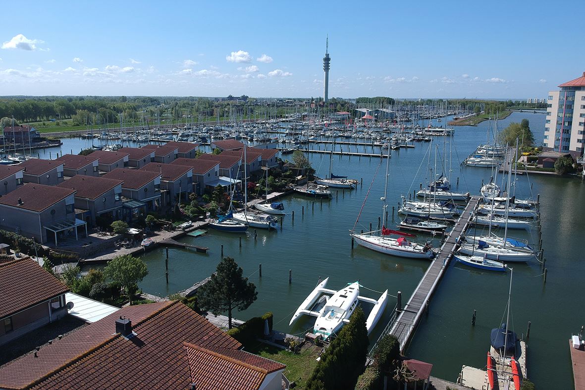
Parkhaven in ice


Planking the second main hull half.

December 24, 2009

Again a fun part to do. Working in the new workshop looks to be much faster due to more space, better equipment, less distraction and less socializing.

And now there are a lot of critical observers (i.e. colleagues). No doubt they will inspect the work on Monday morning to discuss the working rate of their “boss” ………. 😉

Setting up second mainhull half.

(Galery last modified February 21)


Setting up the first main hull half.

November 27, 2006

This is one of these memorable stages. Not only the “real boatbuilding” work,  at least the fun part has just begun in this stage, but more memorable is the fact that the hull fits in my small workshop as I had thought to myself. It’s a close fitting and a relief at the same time.

I’ve started with the starboard side of the main hull as the geometry of this hull half fits better in my workshop.

Starboard mainhull half.

I knew before that the height of the workshop is not enough to join the two main hull halves, so the planning is to make the second hull half and the joining to a complete boat in a bigger workshop somewhere else (still to find that place). This will be temporary and the completing of the boat will be again in my garage.


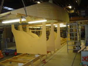
making the last (of 4) float half.

August 8, 2005

Click here or the picture below for the setup, planking and infusion of the fourth float half.

Last float half.


The setup of the second float.

May 22, 2005

It has been a steep learning curve till now, so I hope to built the starboard float much quicker than the first port float (otherwise I have a problem 😉 Here is the photo album.

Second float, the beginnings.

The float pages are now compressed into one page. The building photo’s are published in web albums, which  enabled me to insert several new pictures.


The setup of the second float half.

August 26, 2003

After a holiday break (and a not workable heat wave) now the planking of the second float hull half.

With all these lessons learned it’s becoming high time to start with the second hull half. Because of the limited room in my workshop, I have to make the second hull half of the same float now. This creates an extra setup of the form frames with the fore and aft battens. But I can do this quicker than moving the hull half for storing in another place. The new setup took less than 8 hours.

The hull halves are not symmetric, due to the raised deck area. The form of this half is not “self-releasing”, in other words, the raised deck area “hangs over”. This required an other setup of the battens in that area, which will allow to remove these battens while the hull is still in the form frames. By the way, Ian Farrier recommends to leave this area unlaminated and to bent into shape after removing the hull from the form frames. This is probably easier with hand-lay-up lamination, but not suitable with my resin infusion technique.