Steering Pedestal (2)

September 11, 2014

Click in the image for more photos of the build of the steering pedestal.

Click for gallery
The bevel box that connects the vertical torque tube in the steering pedestal and the horizontal torque tube to the reduction gear box is also the base for the autopilot drive. The bevel box needs a sturdy base but still floats somewhere above the engine. There are various solutions thinkable but I choose to lengthening the steering pedestal tube. This is the main reason why I decided to make the steering pedestal myself.

At first I had wild plans to design my own but at the end I just copied the type 150 of Jefa.

However, I have underestimated the amount work and it took a lot of time. Another complication is that the Jefa tube is an aluminium tube with a wall thickness of about 3mm. or so while my composite construction has a wall thickness of about 20mm. While maintaining the same outside dimensions I made it for myself quite complicated. The dimensions of the bevel boxes with their flanges require extra recesses in the foam. But all in all the result is satisfying.


Trial fit of transmission steering components

March 12, 2014

Now all things fall into place. This afternoon I temporary mounted all steering components to see if it works as expected. It has become a very nice and robust steering system. My initial doubts have disappeared and I am pleased with the results. Click in the image below to find the updated photo gallery.

Click for photo gallery


Steering pedestal

March 7, 2014

I’ve decided to make the steering pedestal by myself but limited the design work for the steering pedestal to a few rough sketches. I will do the further details “on the job”. Click in the photo below to see the beginnings of the making of the steering pedestal. To be continued …

Click for photo gallery

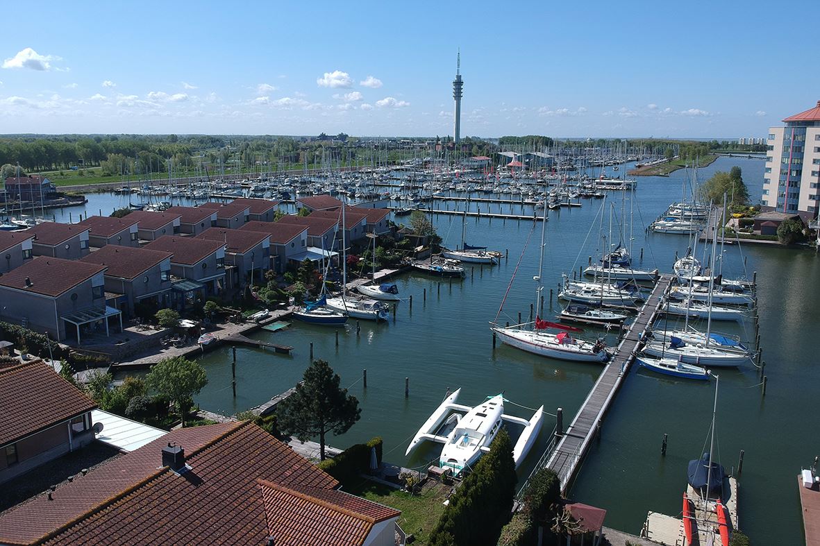
By the way, I installed a new toy, a webcam with a view on my back yard, added at the right of this page. The place is temporary occupied by Noreen, a fast and beautifull F36.


Jefa transmission steering system.

February 11, 2014

Not much visible progress after the last infusion

That doesn’t mean nothing has happened. I’ve punished my brains about the steering system. The choice for a wheel has been made. The distance between wheel and rudder is almost 3m and the waterballast tank is in between. I made a mock-up for a rack & pinion system to see if I can make an optimum use of Jefa’s wide angle geometry. This smart geometry results in a very direct steering amidships (where the loads are low) and a more indirect and powerful steering at full rudder (where the loads are maximal). But because of the lack on space behind the stern I couldn’t get the geometry right and for this reason the R&P system didn’t made it till the implementation stage.

A bit of a pity actually.

In my book the only alternative to the R&P system is a transmission system. So together with the very helpful guys of Jefa we sorted out a transmission system with as few as possible couplings.

But also with this system the room behind the stern and also in relation with the upcoming hull bottom and sides there is ample room for the reduction gear box with the consequence that the position of the torque tube doesn’t match with the height of the cabin bed. The torque tube is intended to go underneath the bed bottom.

Transmissiondrawing

The solution is to position the whole rudder 96 mm further forwards. This means that the wideness of the lower step in the stern has to change from 374 to 278 mm. Resulting in a 210 mm. extension of the reduction gearbox shaft and a recess in the stern for the placement of the reduction gear box as low as possible.

Below is the final design and ordered Jefa parts. The bevel reduction gearbox is housed in its own watertight compartment and separated from “outside” by a watertight roller bearing.

Bevel reduction gearbox

Jefa transmission system parts

Another advantage of the transmission system is that the integration of the autopilot drive is very easy. For this reason the bevel box has an integrated connection shaft at the front.

autopilotdrive

Now this looks more like what I was looking, a nice compact setup with minimal couplings and an integrated autopilot drive unit.

To minimize the amount of couplings I wanted only one bevel box for the connection with the torque tube. However, in the drawing this bevel box is still flying about 350mm under the cockpit floor. This area is the domain of the engine and making a support construction to the sides of the engine room is not very attractive. In my opinion it is better to make an integrated composite construction that is connected with the cockpit floor and thinking about this I came to the conclusion that a longer steering pedestal, that extends under the cockpit floor, will create a sturdy support for the bevel box.

At the moment of writing this solution is on my design board and the whole steering pedestal will now be built in composite by myself.

First step now is to mount the bevel reduction gearbox in the stern. Some temporary wooden slats keep the base plate with the Jefa reduction gearbox level and square until the epoxy glue is cured.

Click for photo gallery


Steering

September 1, 2013

Designer Ian Farrier provides various options for the steering possibilities for the F39. Unfortunately none of these meets my needs.

Steering

There are two kinds of sailors. Those who like tillers and those who like wheels.  First of all there is the choice for tiller or wheel. Just like everything else to do with boats, the wheel/tiller debate is highly subjective. Both systems have their own pro’s and con’s. I always had boats with tiller steering. For me this alone is a good reason for a change. One of the advantages of a tiller, the simplicity with only a few moving parts, is not going to work in the F39 centre cockpit. Like the wheel steering a tiller also needs some kind of mechanical transmission to the rudder stock.

Then there is the aspect of space. The tiller devides the cockpit in a starboard and port part. In this rather small cockpit this compromises access to the coveted space under the dodger. The wheel on the other hand devides the cockpit in a fore and an aft part. The helmsman has is own part of the cockpit. I love that more than a sweeping tiller. Standing behind a wheel while maneuvering in close quarters is more comfortable than with the tiller between the knees. So, for me enough reasons to go on with a wheel.

Now what size? A wheel with a size small enough to walk along is not what I want. In that case I would have bought a sports boat 😉 So as big as possible which turned out to be 900 mm. at a height of 800 mm.

As now these basic questions have been answered the next step is the most difficult one. The decision about the transmission system. Roughly there are four basic types:

Cable or rope steering – in my opinion too prone for faults so not for me;
Hydraulick steering – no rudder feel, also not for me;
Transmission steering – sound and good rudder feeling;
Rack and Pinion steering – sound and straight forward.

I prefer one of the last two systems with first choice the rack and pinion system. At this time the rack and pinion system is subject of study. Some photos and thoughts in the steering study page.