Obligations, having fun or building Fram

September 18, 2011

Besides all kind of obligations there were also a lot of temptations, like enjoying a holiday in Spain, or sailing with Blind Date or with Gary’s F36, or just having family fun, or …. all responsible for the slow progress lately.

And no Gary, I did not fall for your trap to buy that F27 to play with to  induce a further delay to participate in the regattas with my F39 😉

In the mean time I still manage to do some things on Fram and you can find the latest photo’s by clicking the following links:

– Sterntube, now finished with a nice shaped kevlar laminate
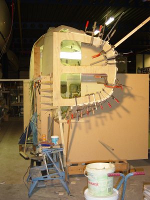
– Mainhull, all kinds of small jobs, like the for now finished wingnet flange

Next update is starting with the outside hull laminate (about 6 months later than planned at first 😦


F-40 instead of F-39 trimaran ?

January 30, 2011

I made the second (Port) main hull half a little longer in the stern. This was not possible in my previous workshop due to the lack of space. After joining the two halves I decided to make an extension on the Starboard half to make both hull halves the same length. I don’t know yet if I will leave the hull one feet longer, but doing this now in this stage is quite easy and I can always decide afterwards to cut it off.

Click for photo gallery

The installation of the prop shaft is now ready and some new photo’s are here.


Smoothing out the ride with a thrust bearing drivetrain and overdrive prop

January 17, 2011

Constant velocity or CV joints are one of those marvels of modern engineering that are exceedingly simple yet brilliant. Known in the engineering world as a “homokinetic” (meaning “same motion”) joint, CV joints are also used in many industries and in the field of transportation

The propeller shaft is aligned to an thrust bearing, which absorbs the propeller thrust. A CV shaft transmits engine power to the thrust bearing and propeller shaft. The CV shaft automatically adjusts to changes in the alignment between engine and thrust bearing and allows engine movements in every direction. 

Aquadrive

The primary mission is to support high axial and radial loads while transmitting rotational energy. This means a thrust bearing supports the fore and aft or axial thrust from the propeller, as well as the spinning loads imparted by the rotating shaft, while allowing the shaft to spin with minimal friction.

This way the engine’s motor mounts are no longer compressed by propeller thrust, and, as such, they can be designed much differently than those used for vibration isolation as well as transmission of thrust. Motor mounts that are used in conjunction with thrust bearing systems may be especially “soft,” which means they are considerably more effective when it comes to absorbing engine vibration.  So, by isolating the engine from the rest of the boat, noise and vibration are greatly reduced.

Click for photogallery

In combination with the two speed (overdrive) Gori prop I hope with this system to have minimized the engine vibrations. By the way, the Gori prop has arrived. Click in the above picture to see the trial fit.


Stern tube installation.

December 24, 2010

I finally made a decision about what kind of propeller shaft support bracket to choose. The plans calls for the fin or P type but in my view these have some disadvantages. First, it is not made of composite but of steel, bronze or brass . This means a different material that sticks out of the hull with risk of leakage as it is a subject for high forces. To me it also looks quite vulnerable but it has to withstand ropes or netting that can be caught by the propeller but also a stone/rock on the wrong place when drying out.

A  more solid construction is possible with the reinforcement type shaft support, the skeg with build in stern tube. Advantage it is it can be made as a whole with the hull (all composite) but disadvantage is some more drag, more difficult to make and some extra facilities for the water lubrication. I think I can minimize the drag disadvantage by making the skeg as small and thin as possible with a carbon plate as base. The following picture shows the general idea.

Click for photo gallery

Click in the picture for the photo gallery.

The engine page has been updated too and there you can find two photo’s of what can happen with a P- style shaft support bracket when catching a lobster pot rope.